Drainage Gradients Falls
Guide to calculating Falls & Gradients in Drainage
Drainage Gradients Falls
All horizontal drainage pipes, both above and below ground, should be laid to an adequate gradient.
Gradients
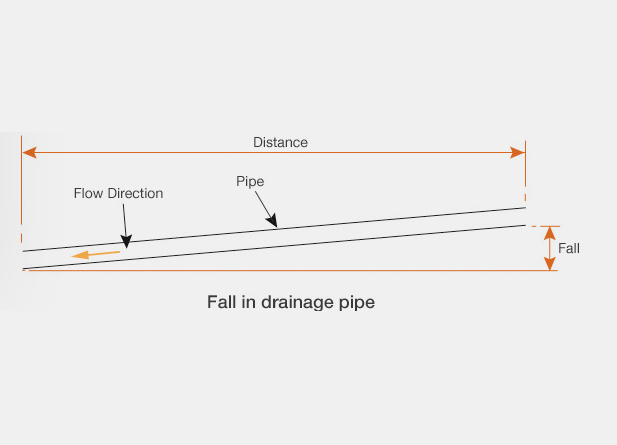
The fall in a pipe may be defined as the vertical amount by which the pipe drops over a distance. The distance can be between sections of pipe or between manholes. The diagram below shows pipe fall and distance.
FALL = GRADIENT X DISTANCE
For example, calculate the fall in a 50 metre section of foul water pipe work if the gradient is to be 1 in 80.
A gradient of 1 in 80 is converted to a number instead of a ratio – 1 / 80 = 0.0125
Fall = 0.0125 x 50
Fall = 0.625 metres or 625mm.
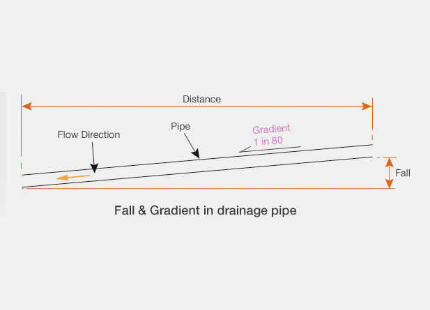
The previous diagram may be completed by adding a pipe gradient.
Falls
The fall in a pipe may be defined as the vertical amount by which the pipe drops over a distance. The distance can be between sections of pipe or between manholes. The diagram below shows pipe fall and distance.
FALL = GRADIENT X DISTANCE
For example, calculate the fall in a 50 metre section of foul water pipe work if the gradient is to be 1 in 80.
A gradient of 1 in 80 is converted to a number instead of a ratio – 1 / 80 = 0.0125
Fall = 0.0125 x 50
Fall = 0.625 metres or 625mm.
The previous diagram may be completed by adding a pipe gradient.
Invert Levels
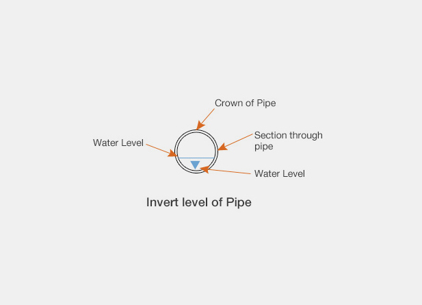
The invert level of a pipe is the level taken from the bottom of the inside of the pipe as shown.
The level at the crown of the pipe = the invert level + internal diameter of the pipe + pipe wall thickness. It may be necessary to use this in calculations when level measurements are taken from the crown of a pipe
Manholes
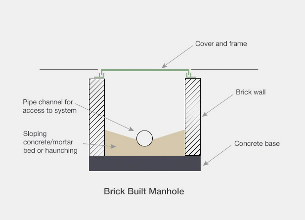
Manholes can be manufactured from masonry or precast concrete. Sometimes several precast concrete rings are used to form a manhole which speeds up the on-site construction process. Step irons may be required to assist access for workmen if manhole is below 1.0 metre in depth.
Manholes and access chambers are also manufactured in PVC. An access chamber is not usually large enough to admit a person but is suitable for access by cleaning rods or hose and is used for domestic applications. A common size of plastic access chamber is 450mm diameter.
For the domestic market plastic, fibreglass or galvanised steel lids may be used but cast iron lids are required where traffic crosses.
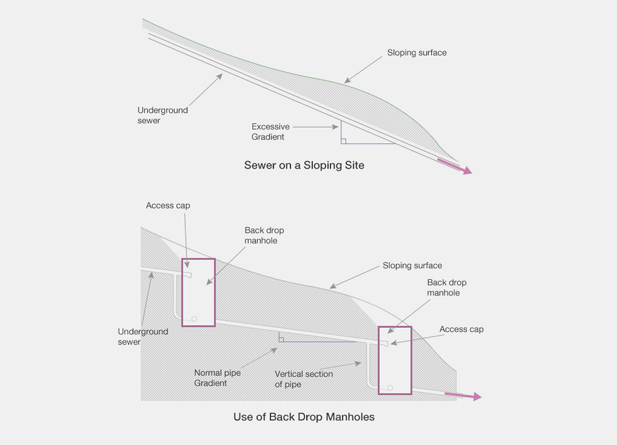
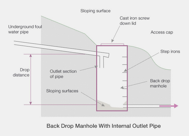
A back drop manhole is used in areas where the surface level slopes as shown below. If the underground sewer pipe is to stay below ground it must follow the average gradient of the slope. This invariably means that the pipe gradient becomes too steep, resulting in the solids being left stranded in the pipe causing a blockage. The back drop manhole was developed to overcome this problem.
Internal vertical sections of pipe can be used as an easier way to construct a back drop manhole.
Why Choose Us?
Choosing Drainage Consultants Limited means choosing a company with over 30 years of experience in delivering high-quality drain repairs. Our team are dedicated to providing the best solutions with minimal disruption to your property. We are proud to offer cost-effective solutions that don’t compromise on quality, ensuring you get the best value for your investment.
Contact Us
Contact Drainage Consultants Limited today for a free quote and let our professionals take care of all your drainage needs. With over 30 years of experience and a dedication to delivering the highest standards of service, you can rest assured that your drainage system is in good hands.
Call us now on 0800 0654 111 to schedule a service or to learn more about how we can assist you with your drain repair needs. Whether you’re a homeowner, a business owner, or a property manager, Drainage Consultants Limited is here to provide the best solution for your drainage problems.

Our Accreditations
Get in touch
To find out more about the services we provide, please get in touch.
Call free on: 0800 065 4111
(Calls are recorded for training and monitoring purposes)
Drainage Consultants Ltd
Clearwater House,
Newby Road Industrial Estate,
Hazel Grove,
Stockport SK7 5DA

